Create an IoT sensor with NodeMCU and Lua
In this post I want to show you how to create your own IoT sensor with the NodeMCU and the Lua programming language. The device called the NodeMCU makes it easy to start reading sensor data, sending it back to another location for processing or aggregation, such as the cloud. We'll also compare the NodeMCU to the Raspberry Pi and talk about the pros/cons of each for an IoT sensor.
Introduction

Picture Wikipedia Creative Commons
NodeMCU is an open source IoT platform. It includes firmware which runs on the ESP8266 Wi-Fi SoC from Espressif Systems, and hardware which is based on the ESP-12 module.
via Wikipedia
The device looks similar to an Arduino or Raspberry Pi Zero featuring a USB port for power or programming and features a dedicated chip for communicating over WiFi. Several firmwares are available (similar to an Operating System) for programming the device in Lua, C (with the Arduino IDE) or even MicroPython. Cursory reading showed the Lua firmware to support the most amount of modules/functionality including HTTP, MQTT and popular sensors such as the BME280.
The documentation for the NodeMCU with Lua is detailed and thorough giving good examples and I found it easy to work with. In my opinion the Lua language feels similar to Node.js, but may take some getting used to. Fortunately it's easy to install Lua locally to learn about flow control, loops, functions and other constructs.
NodeMCU vs Raspberry Pi
The Raspberry Pi Zero runs a whole Operating System which is usually Linux and is capable of acting as a desktop PC, but the NodeMCU runs a firmware with a much more limited remit. A Raspberry Pi Zero can be a good basis for an IoT sensor, but also is rather over-qualified for the task. The possibilities it brings come at a cost, such as relatively high power consumption and unreliable flash storage, which can become corrupted over time.
Its power consumption with WiFi enabled could be anything up to 120 mA even with HDMI and LEDs disabled. In contrast the NodeMCU runs a much more specialised chip with power-saving features such as a deep sleep mode that can make the board run for up to a year with a standard 2500mAh LiPo battery.
Here's my take:
I'm a big fan of the Raspberry Pi and own more than anyone else I know (maybe you have more?), but it does need maintenance such as OS upgrades, package updates and the configuration to set up I2c or similar can be time-consuming. For IoT sensors, if you are willing to learn some Lua the NodeMCU can send readings over HTTP or MQTT and is low-powered and low hassle at the same time.
If you already have a Raspberry Pi and can't wait to get your NodeMCU then you can follow my tutorial with InfluxDB here.
yep, saw your @pimoroni EnviroPhat piece and thought it was Grafana to start with-this is my version pic.twitter.com/YlRjuLMfBk
— Alex Ellis (@alexellisuk) 2 September 2016
Tutorial overview
- Bill of materials
- Create a firmware
- Flash firmware to NodeMCU
- Test the REPL
- Connect to WiFi
- Connect and test the BME280 sensor
- Upload init.lua
- Upload sensor readings to MQTT
- Observe reported MQTT readings on PC/Laptop
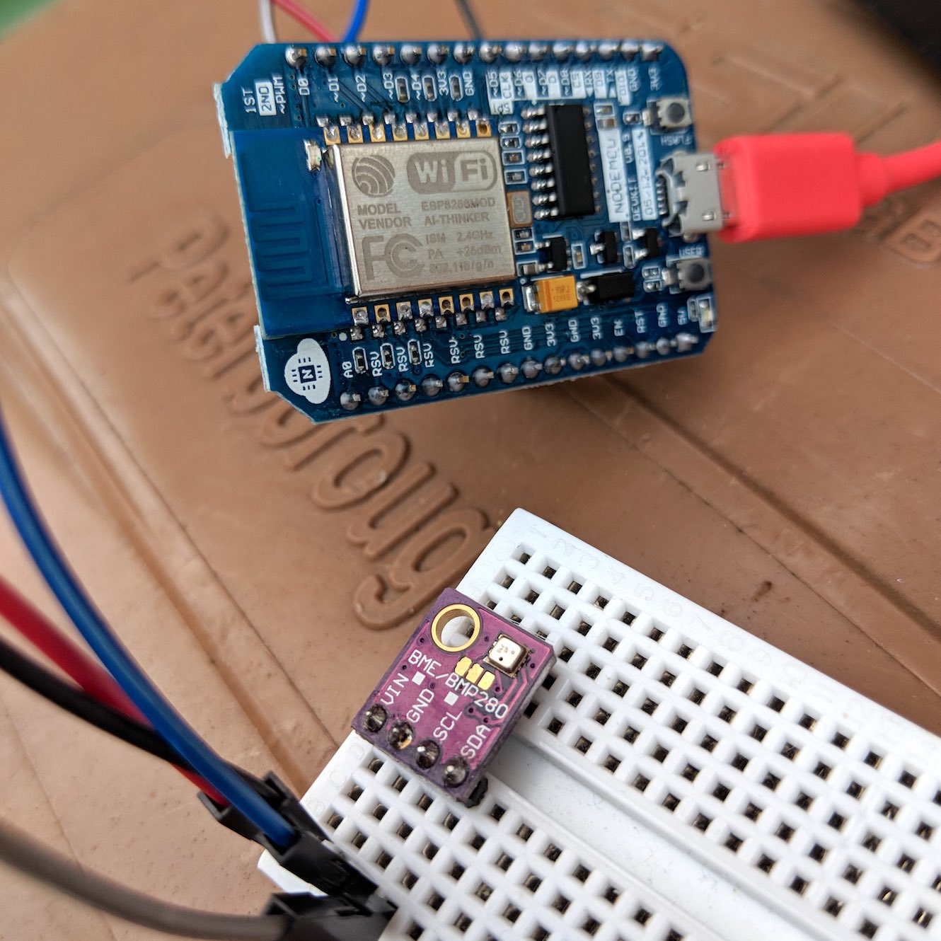
The finished IoT sensor:
Bill of materials
- NodeMCU
You will need to purchase a NodeMCU board. I recommend buying that on eBay, with pre-soldered pins. Aim to spend 4-6 USD.
-
Micro-USB cable
-
BME280 (AliExpress)
I buy these for 3-5 USD on eBay, branded versions are much more expensive.
-
Short male-to-male and male-to-female jumpers
-
Small bread-board
Create a firmware
The NodeMCU chip is capable of supporting dozens of different firmware modules, but has limited space, so we will create a firmware using a free cloud service and then upload to the chip.
-
Head over to https://nodemcu-build.com/
-
Select the stable 1.5 firmware version
-
Pick the following modules: adc, bme280, cjson, file, gpio, http, i2c, mqtt, net, node pwm, tmr, uart, wifi.
You will receive an email with a link to download the firmware.
Flash the firmware
You will need to install a Python script to flash the firmware over the USB serial port. There are various options available and I used esptool.py on a Linux box.
https://nodemcu.readthedocs.io/en/master/en/flash/
This means I typed in:
$ sudo ./esptool/esptool.py -p /dev/ttyUSB0 write_flash 0x00000 nodemcu-1.5.4.1-final-15-modules-2018-07-01-20-30-09-float.bin

final-12-modules-2018-07-01-19-38-04-float.bin
esptool.py v2.4.1
Serial port /dev/ttyUSB0
Connecting....
Detecting chip type... ESP8266
Chip is ESP8266EX
Features: WiFi
MAC: 18:fe:34:a2:8b:0d
Uploading stub...
Running stub...
Stub running...
Configuring flash size...
Auto-detected Flash size: 4MB
Flash params set to 0x0040
Compressed 480100 bytes to 313202...
Wrote 480100 bytes (313202 compressed) at 0x00000000 in 27.6 seconds (effective 139.0 kbit/s)...
Hash of data verified.

Leaving...
Hard resetting via RTS pin...
Test the REPL
Now that the NodeMCU has the Lua firmware flashed you can connect with Linux or Mac to the device in a terminal to enter commands on the REPL.
The device starts off at a baud rate of 115200 which is not useable for typing.
sudo screen -L /dev/ttyUSB0 115200

> uart.setup(0,9600,8,0,1,1)
Now type in Control + A + : then type in quit
Next you can connect at the lower speed and try out a few commands from the docs.
sudo screen -L /dev/ttyUSB0 9600

> print("Hello world")
Hello world
>
Keep the screen session open, you can suspend it at any time by typing Control A + D and resume with screen -r.
Connect to WiFi
Next let's try to connect to the WiFi network and get an I.P. address so that we can access the web.
ssid="SSID"
key="key"

wifi.setmode(wifi.STATION)
wifi.sta.config(ssid, key)
wifi.sta.connect()
tmr.delay(1000000)

print(string.format("IP: %s",wifi.sta.getip()))

IP: 192.168.0.52
Now that you have the device IP you should be able to ping it with ping -c 3 192.168.0.52
Since we built-in the HTTP stack we can now access a web-page.
Go to https://requestbin.fullcontact.com/ and create a "Request Bin"
Now type in the code below changing the URL to the one provided to you by the website. When you refresh the web-page, you should see the data appear on the page showing the WiFi signal "RSSI".
binURL="http://requestbin.fullcontact.com/13651yq1"
http.post(binURL,
  'Content-Type: application/json',
  string.format('{"rssi": %d}', wifi.sta.getrssi()),
  function(code, data)
    if (code < 0) then
      print("HTTP request failed")
    else
      print(code, data)
    end
  end)
In my example I saw the data {"rssi": -64} appear on the UI showing a good/low noise level due to proximity to my access point.
Connect and test the BME280 sensor
According to mqtt.org, MQTT is:
.. a machine-to-machine (M2M)/"Internet of Things" connectivity protocol. It was designed as an extremely lightweight publish/subscribe messaging transport. It is useful for connections with remote locations where a small code footprint is required and/or network bandwidth is at a premium.
If you've ever used a message queue before then this will be familiar territory, but if it's new then you can either publish messages or subscribe to them for a given topic.
Example: a base station subscribes to a topic called "sensor-readings" and a series of NodeMCU / IoT devices publish sensor readings to the "sensor-readings" topic. This de-couples the base-station/receiver from the IoT devices which broadcast their sensor readings as they become available.
We can use the public Mosquitto test MQTT server called test.mosquitto.com - all readings will be publicly available, but you can run your own Mosquitto MQTT server with Docker or Linux later on.
Now power off the device by unplugging the USB cable and connect the BME280 sensor.
I suggest making all these connections via the breadboard, but you could also connect them directly:
- Connect positive on the BME280 to 3v3 on the NodeMCU
- Connect GND on the BME280 to GND on the NodeMCU
- Connect SDA on the BME280 to to pin D3 on the NodeMCU
- Connect SDC on the BME280 to to pin D3 on the NodeMCU
Now power up and get into 9600 baud again, opening the screen and REPL so we can test the sensor.
sda, scl = 3, 4
mode = bme280.init(sda, scl)
print(mode)
tmr.delay(1000000)
H, T = bme280.humi()
t = T / 100
h = H / 1000
ip = wifi.sta.getip()
if ip == nil then
    ip = "127.0.0.1"
end
RSSI=wifi.sta.getrssi()
if RSSI == nil then
    RSSI=-1
end

msg = string.format('{"sensor": "s1", "humidity": "%.2f", "temp": "%.3f", "ip": "%s", "rssi": %d}', h, t, ip, RSSI)
print(msg)
If the connections were made correctly then you will now see a JSON message on the console.
Upload init.lua
Download init.lua from my GitHub Gist and then update the WiFi SSID (mySsid) and Password settings (myKey).
https://gist.github.com/alexellis/6a4309b316a1bc650e212d6d4f47deea
Find a compatible tool to upload the init.lua file, or on Linux use the same tool I used:
sudo nodemcu-uploader --port=/dev/ttyUSB0 upload ./init.lua
Various tools are available to upload code: https://nodemcu.readthedocs.io/en/dev/en/upload/
Upload sensor readings to MQTT
Now unplug your NodeMCU and find a small USB power pack or phone charger and plug the device in. It will run init.lua and start transmitting messages to test.mosquitto.com over MQTT.
Observe reported MQTT readings on PC/Laptop
Install an MQTT client on Linux or find a desktop application for MacOS/Windows.
On Debian/Ubuntu/RPi you can run: sudo apt-get install mosquitto-clients
Then listen to the server on the topic "sensor-readings":
mosquitto_sub -h test.mosquitto.org -p 1883 -t sensor-readings -d
Example of data coming in from my sensor in my garden:
Subscribed (mid: 1): 0
...
Client mosqsub/19950-alexellis received PUBLISH (d0, q0, r0, m0, 'sensor-readings', ... (108 bytes))
{"sensor": "s1", "humidity": "58.38", "temp": "24.730", "ip": "192.168.0.51", "vdd33": "65535", "rssi": -75}
Client mosqsub/19950-alexellis received PUBLISH (d0, q0, r0, m0, 'sensor-readings', ... (108 bytes))
{"sensor": "s1", "humidity": "57.96", "temp": "24.950", "ip": "192.168.0.51", "vdd33": "65535", "rssi": -75}
...
Wrapping up
You've now built a robust IoT sensor that can connect over your WiFi network to broadcast sensor readings around the world.
Take it further by trying some of these ideas:
- Add WiFi re-connection code
- Use deep sleep to save power between readings
- Aggregate the readings in a time-series database, or CSV file for plotting charts - try my environmental monitoring dashboard
- Run your own MQTT server/broker
- Try another sensor such as an LDR to measure light
- Build an external enclosure and run the device in your garden
If you liked this tutorial or have questions then follow me @alexellisuk on Twitter.
Share on Twitter
Create an IoT environmental sensor with NodeMCU and Lua https://t.co/esgaeqrKwq pic.twitter.com/hm7sWIi3AF
— Alex Ellis (@alexellisuk) July 9, 2018